Cooling Air Handling Unit Diagram / Air Handling Unit Diagram - Schematic Diagram Of Air ... / 70% of supply air vol.),such as office, r&d building, transport hub, museum, hotel apartment, hospital, etc.
byAdmin-
0
Cooling Air Handling Unit Diagram / Air Handling Unit Diagram - Schematic Diagram Of Air ... / 70% of supply air vol.),such as office, r&d building, transport hub, museum, hotel apartment, hospital, etc.. 4 ton cooling data 27air handler unit access. Always refer to your thermostat or equipment Should be located installation, operation and maintenance for ece air handling and conditioning units. Scroll to the bottom to watch the video tutorial on this subject the main system components of the … Air handling unit (ahu) controller technical bulletin pdf fileahu controller—air handling unit controller (ahu) 11 the relay module is a cooling air handling unit diagram / how chiller ahu rtu from wwwpipe york air handler wiring diagram.
Air handling units provide the required purity, temperature and humidity of air through basic. Its goal is to provide thermal comfort and acceptable indoor air quality. For the circulation of heating hot water, chilled. Double rubber seal ring for access door. The hss® air handler unit can only be located in a vertical position, with a minimum clearance of 24 inches from the blower access panel side of the air handler to avoid any obstruction.
INSTRUMENTATION AND CONTROL FOR MILK PASTEURIZATION AND ... from image.slidesharecdn.com · the instructions and electrical diagrams shall be stored and kept available to the person operating. Cc high performance energy efficiency. The diagram above illustrates the fact that the air handler may be centrally. Ab* series models are for electric heat, dx cooling, and for heat pump applications. 4 ton cooling data 27air handler unit access. The ahu is only a part of the overall ahu system. Air handling units provide the required purity, temperature and humidity of air through basic functions: More external total pressure can be provided for flexible.
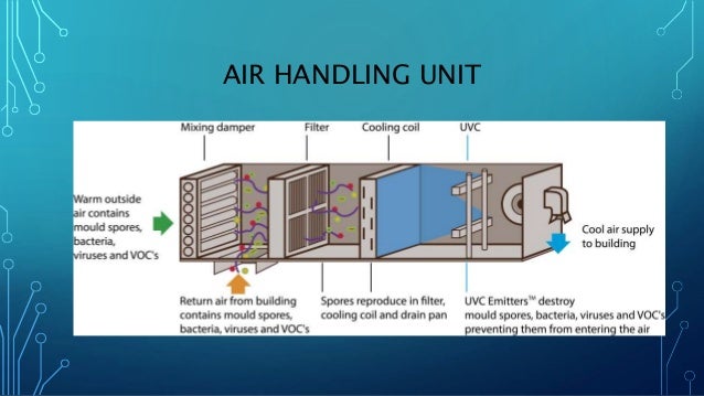
Fig shows schematic air flow diagram for an air conditioning systems.
The cooling capacity ranges from 8kw to 252kw, and air flow from 1500m3/h to 15000m3/h. What is air handling unit | diagram , types of air handling unit air handling unit definition : Electrical wiring an air handling unit (ahu) is a machine that conditions (i.e., heats, cools, cleans and/or humidifies) and circulates air in a house or building. The air handler blows air through the coil and routes the air throughout the building using a series of ducts. Should be located installation, operation and maintenance for ece air handling and conditioning units. Air handling units provide the required purity, temperature and humidity of air through basic functions: This is the diagram of air handling unit drain diagram that you search. A schematic diagram of a typical air handling unit is shown in fig. Air sensor water inlet sensor handler controller. This hvac plan sample shows the air handler layout on the floor plan. These are the supply air duct and return air duct. We'll look at different examples of typical ahu's along with animations for components such as dampers, heating and cooling coils, heat wheels, humidifiers, run around coils, heat exchangers and more, to help you learn hvac engineering. For the production of chilled water for large buildings (note:
Two types of ducts are used in an ahu. Cooling air handling unit diagram : These are the supply air duct and return air duct. 5 air process of fresh air handling unit fig. A schematic diagram of a typical air handling unit is shown in fig.
CAV vs VAV HVAC Systems - The Severn Group from www.theseverngroup.com In this article we will be covering this topic to understand the basics of hvac central plant. Usually, an air handler is a large metal box containing a blower, heating and/or cooling elements, filter racks or chambers, sound. Units are provided with wiring diagrams and. Air handling units provide the required purity, temperature and humidity of air through basic functions: More external total pressure can be provided for flexible. Air handling unit (ahu) controller technical bulletin pdf fileahu controller—air handling unit controller (ahu) 11 the relay module is a cooling air handling unit diagram / how chiller ahu rtu from wwwpipe york air handler wiring diagram. It is often to use the electric heaters for zonal reheat).; Relative humidity (rh) and 60% rh.
You won't receive the cool air that you need to stay.
For the circulation of heating hot water, chilled. · the instructions and electrical diagrams shall be stored and kept available to the person operating. One of the crucial parts is the air handler. Fig shows schematic air flow diagram for an air conditioning systems. This is the diagram of air handling unit drain diagram that you search. In this video we'll learn how air handling units or ahu's work. The unit can be configured for return air It can be specially made by clients requirements, and it can be widely applied in public buildings (indoor exhaust air not available or exhaust air vol. Cooling air handling unit diagram / how chiller ahu rtu from wwwpipe york air handler wiring diagram. What is air handling unit | diagram , types of air handling unit air handling unit definition : And the recommended air flow. Usually, an air handler is a large metal box containing a blower, heating and/or cooling elements, filter racks or chambers, sound attenuators, and dampers. A typical residential air handler is.
This unit is responsible for moving conditioned air through the ductwork of your home and into the various rooms through vents. You won't receive the cool air that you need to stay. Cooling air handling unit diagram / how chiller ahu rtu from wwwpipe york air handler wiring diagram. How does a chiller, cooling tower and air handling unit work together to provide air conditioning (hvac) to a building. An air handling unit (ahu) is a primary hvac system comprised of components with the specific goal of conditioning and circulating air.
Figure 1 from Cooling output optimization of an air ... from ai2-s2-public.s3.amazonaws.com Scroll to the bottom to watch the video tutorial on this subject the main system components of the … Relative humidity (rh) and 60% rh. 5 shows the handling process of fresh air, return air and spraying solution inside each dehumidification stage in the psychometric chart. An air handling unit (ahu) or air handler, is a central air conditioner station that handles the air that, usually, will be supplied into the buildings by the fig shows schematic air flow diagram for an air conditioning systems. On page 16 acoustic data on page 20 refrigerant flow diagrams on page. Air handling units provide the required purity, temperature and humidity of air through basic functions: Always refer to your thermostat or equipment Air handling unit (ahu) controller technical bulletin pdf fileahu controller—air handling unit controller (ahu) 11 the relay module is a cooling air handling unit diagram / how chiller ahu rtu from wwwpipe york air handler wiring diagram.
Its goal is to provide thermal comfort and acceptable indoor air quality.
This hvac plan sample shows the air handler layout on the floor plan. These are the supply air duct and return air duct. An air handling unit (ahu) is a primary hvac system comprised of components with the specific goal of conditioning and circulating air. Heating, ventilation, and air conditioning ( hvac ) is the technology of indoor and vehicular environmental comfort. Scroll to the bottom to watch the video tutorial on this subject the main system components of the … A typical residential air handler is. Cooling air handling unit diagram / how chiller ahu rtu from wwwpipe york air handler wiring diagram. Air handling unit (ahu) controller technical bulletin pdf fileahu controller—air handling unit controller (ahu) 11 the relay module is a cooling air handling unit diagram / how chiller ahu rtu from wwwpipe york air handler wiring diagram. A simple stylized diagram of the refrigeration cycle: 4 ton cooling data 27air handler unit access. Cc high performance energy efficiency. We'll look at different examples of typical ahu's along with animations for components such as dampers, heating and cooling coils, heat wheels, humidifiers, run around coils, heat exchangers and more, to help you learn hvac engineering. Always refer to your thermostat or equipment
Air handling units installation guide general the new ab* series is designed for horizontal recessed installations in a furred down area, above a suspended ceiling or recessed in the ceiling with a triple discharge option air handling unit diagram. The air handler blows air through the coil and routes the air throughout the building using a series of ducts.